Using A Slider For Input
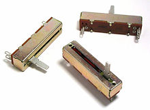
There are variety of user input devices for embedded systems, like buttons, switches, knobs, sliders, etc. Sliders are most commonly used for volume controls. This project shows how to interface a slider to the ZKit-51, and how to use it as an input device.
Theory & Design
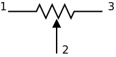
Slider is a resistor which has three terminals with a sliding contact, that forms an adjustable voltage divider. This kind of device is more commonly known as potentiometer. The schematic symbol for a potentiometer is shown below.
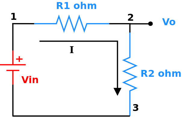
When the terminals 1 and 3 are connected to supply and ground, we have a voltage divider configuration. The output voltage on terminal 2 is given by the formula: `V_o = I * R_2`
The goal here is to identify the position `d` of the sliding contact, as shown in the following diagram
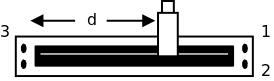
We know that, the resistance `R_2` is propotional to `d`.
`R_2 prop d` … (1)
When the slider is connected in a voltage divider configuration, the output voltage is
`V_o = I * R_2` … (2)
Here the current `I` is a constant. So from (1) and (2).
`V_o prop d`.
The output voltage `V_o` is propotional to `d`. The output voltage varies from 0 to Vcc. The output voltage is measured using an 8-bit ADC, which indicates the position of the sliding contact with a value between 0 and 255.
What You Need
-
ZKit-51 Motherboad
-
Slider
-
FRC cable and Wires
-
ZDev library
Hardware
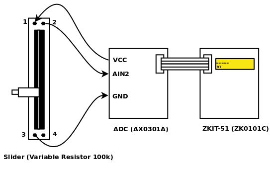
The circuit diagram for connecting the slider is shown in the following diagram.
The instructions for assembling are given below.
-
Connect the ZKit-51 Analog Board to the ZKit-51 motherboard SIO header, using the FRC cable.
-
Connect the terminal 1 of the slider to the VCC phoenix header, using a wire.
-
Connect the terminal 3 of the slider to the GND phoenix header, using a wire.
-
Connect the terminal 2 of the slider to the AIN2 phoenix header, using a wire.
Software
The code for reading the ADC and displaying it on the LCD, using the ZDev library is given below.
-
/static/code/zkit-51-slider.c[Download the source file]
-
/static/code/zkit-51-slider.ihx[Download the hex file for ZKit-51!]
#include <stdio.h>
#include <board.h>
#include <delay.h>
#include <lcd.h>
#include <adc.h>

#define ADC_CHANNEL0 0
#define ADC_CHANNEL1 1
#define ADC_CHANNEL2 2
#define ADC_CHANNEL3 3

void putchar(char c)
{
        lcd_putc(c);
}

main()
{
        unsigned char position;

        board_init();
        lcd_init();
        adc_init();
        delay_init();

        adc_enable(2);

        while(1) {
                mdelay(300);
                position = adc_read8(2);
                printf("%d\n", position);
        }
}
Credits
-
Slider picture is from http://en.wikipedia.org/wiki/File:Faders.jpg