Robot Framework in Automotive Electronics Testing
With advancements in technology and increasing customer demands, automotive ECUs have become incredibly complex, to a point where a fairly advanced vehicle can have more than a thousand features, provided by a hundred ECUs.
This complexity has necessitated OEMs to rethink their vehicle testing strategy. Python and Robot Framework are now playing an increasingly dominant role in a realm that was dominated by proprietary software tools. In this article, we will discuss how Python and Robot Framework can be used in automotive testing, using an OBD-II Heads-up Display, as an example.
Introduction
Vehicle Networks
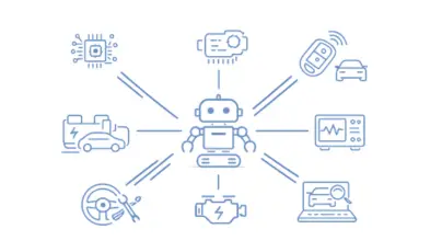
A vehicle has an intricate network of embedded computers that work together in tandem to achieve various vehicle functionalities.
These embedded systems manage a wide range of functionalities, such as:
-
Displaying real-time vehicle information on the driver dashboard.
-
Delivering navigation guidance through GPS and mapping software.
-
Providing seamless infotainment via Bluetooth-connected devices.
-
Managing vehicle access with automated locking and unlocking system.
-
Ensure the safety of passengers by deploying airbags when a vehicle collision is detected.
Each of these embedded computers that are part of this vehicle network is called an Electronic Control Unit or ECU.
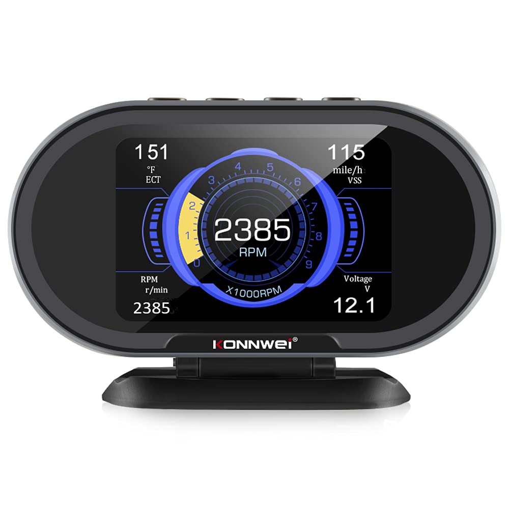
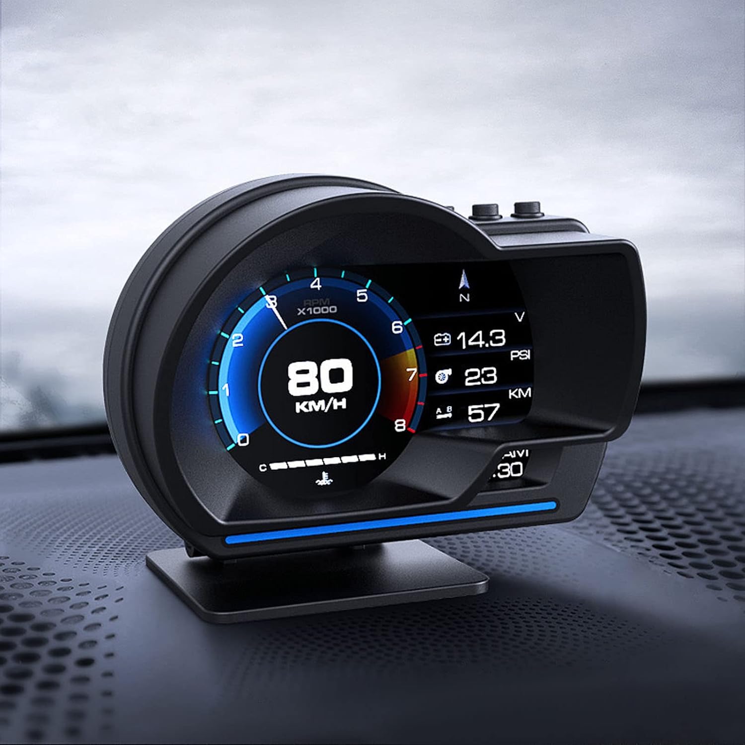
HUD Digital Cluster
The ECU we will use for our demonstration is an off-the-shelf HUD Digital Cluster. This can be purchased from Amazon, and can be connected to any modern vehicle. The HUD Digital Cluster once connected becomes part of the vehicle network and can collect and display vehicle parameters on its display.
Introduction to OBD-II
The way HUD Digital Cluster works is by connecting to the OBD-II port of a vehicle. The OBD-II is a specification developed in 1994 to provide a standardized way of accessing vehicle information. OBD stands for On-Board Diagnostics. It was initially introduced for the purpose of emission testing, but was later extended for obtaining a variety of vehicle data. The OBD-II was made mandatory for vehicles in the US in 1996. Since then OBD-II specification has gone through multiple revisions and improvements. In its current form, OBD-II supports 5 protocols :
-
CAN Bus
-
The Keyword Protocol 2000: KWP2000
-
Variable Pulse Width: J1850 VPW (used by GM cars)
-
Pulse Width Modulation: J1850 PWM (used by Ford cars)
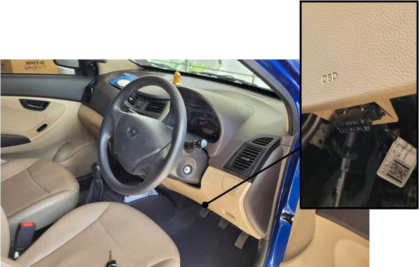
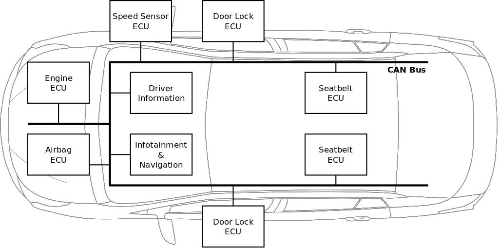
The CAN interface is the latest addition to OBD-II specification and was made mandatory for cars in the US in 2008. The OBD-II port was made mandatory for vehicles in India in 2013.
The CAN is a bus protocol, where multiple nodes are connected in network. These nodes send 8-byte messages to other nodes in the network, in a broadcast fashion. For example a speed sensor node could periodically broadcast the vehicle speed information to other nodes. The dashboard node would pick the speed information and display it on the vehicle dashboard.
Automating the DUT with Python
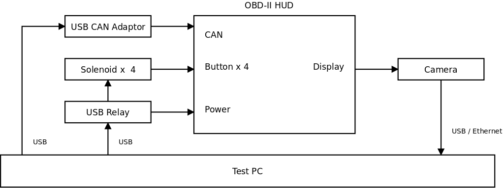
The device under test has three interfaces:
-
Display
-
4 x Buttons
-
OBD-II
-
Power
Each of these interfaces needs to be automated, to be to able test the device. The automation is done through a combination of hardware tools and software libraries.
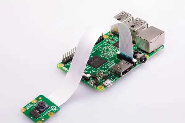
The display can be captured using a camera, then processed using OpenCV and Tesseract to read the information shown on the screen. In this setup, we use a Raspberry Pi Camera and a Raspberry Pi.
The following Python API is made available for the display:
-
img = Display.take_screenshot()
-
img = Display.crop(img, rect)
-
text = Display.ocr(img)
The buttons can be automated through a Push-Pull Solenoid. A solenoid has a coil of wire, a metal plunger, and a spring. The solenoid when energized, creates a magnetic field that attracts the metal plunger. When the solenoid coil is de-energized, the spring retracts the metal plunger.
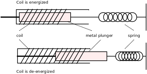
We position 4 solenoids over the 4 buttons, to press and release the button, using the solenoid. The solenoids can be turned ON and OFF through a Relay hardware connected to the test PC.
The following Python API is made available for the buttons:
-
Button.short_press(name)
-
Button.long_press(name)
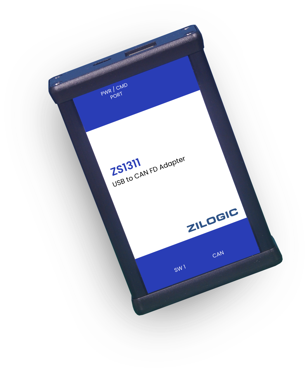
The OBD-II interface can be accessed through a CAN to USB adaptor. This adaptor can be accessed through the Python module python-can. Using this Python module it is possible to write a program that can respond to OBD-II requests, coming from the OBD2 HUD device.
The following Python API is made available for OBD-II:
-
VehicleSim.start_vehicle_simulation()
-
VehicleSim.set_vehicle_param(key, value)
The power to the DUT is controlled through a Relay hardware connected to the test PC.
-
Power.turn_on_dut()
-
Power.turn_off_dut()
The setup block diagram that is shown below.
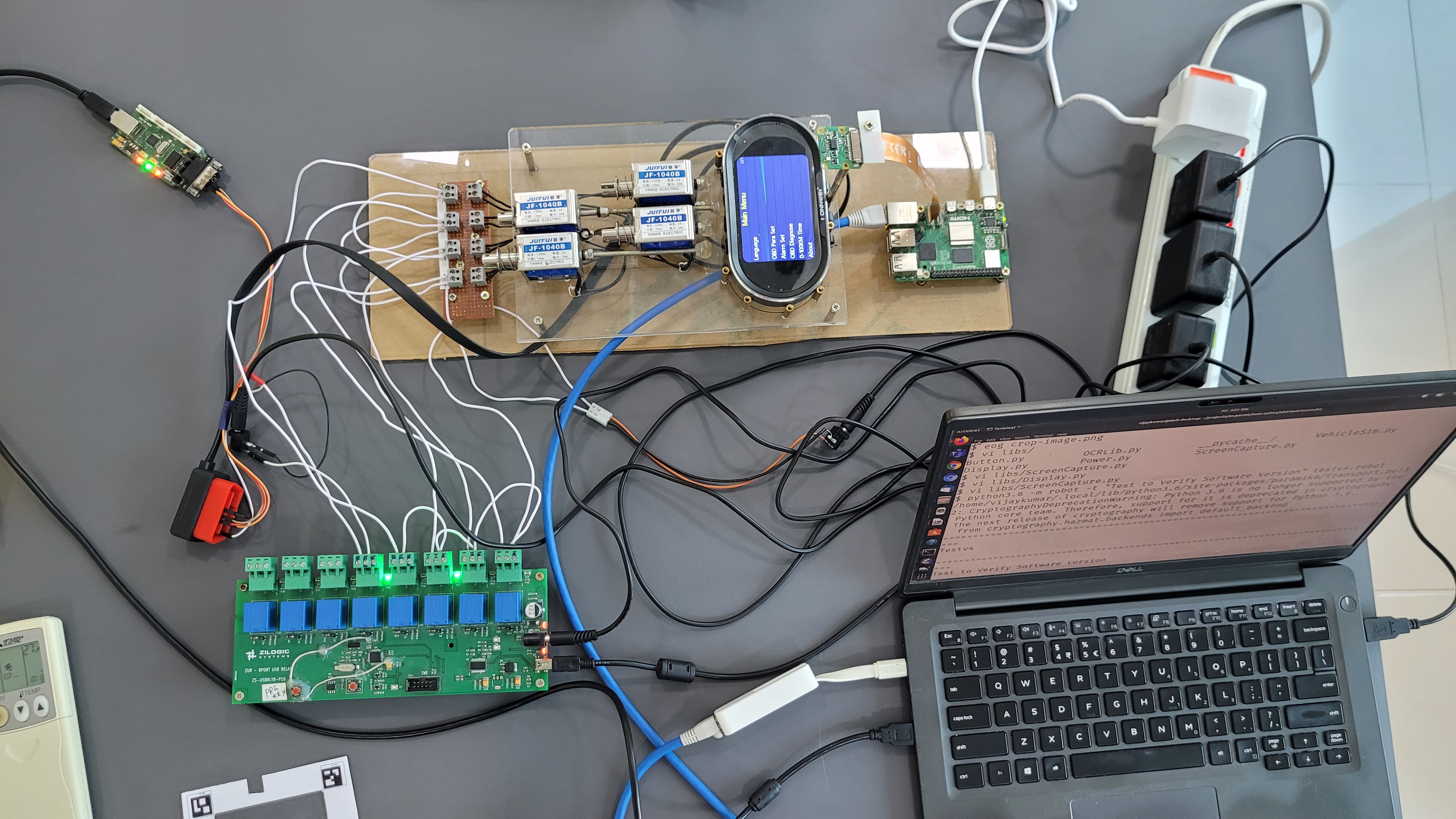
A picture a fully constructed setup is provided below.
Writing Test Cases in Robot Framework
Let’s consider the following BDD test case, and see how we can implement this using Robot Framework and the above keyword libraries.
Given the DUT is ON and Engaged
When the vehicle is moving at 100kmph
Then verify speed gauge displayed speed >= 100kmph
And verify speed gauge displayed speed <= 105kmph
The test case can be written in Robot format as shown below.
*** Settings ***

Library  VehicleSim
Library  Display
Library  Button
Variables  setup-config.yml
Test Teardown  Reset to Default

*** Keywords ***

Reset to Default
    Sleep  5
    Stop Vehicle Simulation
    Turn OFF DUT

Given DUT is ON and Engaged
    Connect to Relay  ${button_serialdev}
    Set Channel  ${can_channel}
    Start Vehicle Simulation
    Turn ON DUT
    Configure RPI  ${hostname}  ${username}  ${password}

When Vehicle is Moving at 100kmph
    Set Vehicle Param  speed  100
    Sleep  10sec

Get Displayed Speed
    Take Screenshot
    Crop  ${img}  ${speedgauge_region}
    ${text}=  OCR  ${image}
    ${speed}=  Convert to Integer  ${text}
    RETURN  ${speed}

And verify speed gauge displayed speed <= 105kmph
    ${speed}=  Get Displayed Speed
    Should be True  ${speed} <= 105

Then verify speed gauge displayed speed >= 100kmph
    ${speed}=  Get Displayed Speed
    Should be True  ${speed} >= 100

*** Test Cases ***

Test to Verify Vehicle Speed Display
    Given DUT is ON and Engaged
    When vehicle is moving at 100kmph
    Then verify speed gauge displayed speed >= 100kmph
    And verify speed gauge displayed speed <= 105kmph
Demo Video
Test Suite Walkthrough
A test suite in Robot Framework has 3 sections: Settings, Keywords and Test Cases. We will focus on the Test Cases section. The test cases section has one test case, consisting of 4 keyword invocations. Each keyword specifies an operation to be performed. The keyword invocations are like function invocations in Python.
A test case contains two kinds of keywords
-
Action keywords
-
Verification keywords
A test case is considered to have failed if any of the keywords raises an exception. Action keywords are invoked to generate input to the DUT, they generally raise an exception if the action could not be performed. Verification keywords are invoked to verify the output from the DUT. They raise an exception if the verification fails. If any of the keywords in the test case raises an exception, the test is considered to have failed.
Adding More Test Cases
Let’s modify the test suite to have two test cases for speed, one for 50kmph and another for 100kmph.
*** Settings ***

Library  VehicleSim
Library  Display
Library  Button
Variables  setup-config.yml
Test Teardown  Reset to Default

*** Keywords ***

Reset to Default
    Sleep  5
    Stop Vehicle Simulation
    Turn OFF DUT

DUT is ON and Engaged
    Connect to Relay  ${button_serialdev}
    Set Channel  ${can_channel}
    Start Vehicle Simulation
    Turn ON DUT
    Configure RPI  ${hostname}  ${username}  ${password}

Vehicle is Moving at ${speed}kmph
    Set Vehicle Param  speed  ${speed}
    Sleep  10sec

Get Displayed Speed
    Take Screenshot
    Crop  ${img}  ${speedgauge_region}
    ${text}=  OCR  ${image}
    ${speed}=  Convert to Integer  ${text}
    RETURN  ${speed}

Verify speed gauge displayed speed <= ${expected}kmph
    ${displayed}=  Get Displayed Speed
    Should be True  ${displayed} <= ${expected}

Verify speed gauge displayed speed >= ${expected}kmph
    ${displayed}=  Get Displayed Speed
    Should be True  ${displayed} >= ${expected}

*** Test Cases ***

Test to Verify Vehicle Speed Display 100
    Given DUT is ON and Engaged
    When vehicle is moving at 100kmph
    Then verify speed gauge displayed speed >= 100kmph
    And verify speed gauge displayed speed <= 105kmph

Test to Verify Vehicle Speed Display 50
    Given DUT is ON and Engaged
    When vehicle is moving at 50kmph
    Then verify speed gauge displayed speed >= 50kmph
    And verify speed gauge displayed speed <= 52kmph
The keywords have been modified to accept embedded arguments. This allows keywords to mimic natural english, with keyword definitions still being generic.
Let’s add another test case to get the version of the device from the about screen.
*** Settings ***

Library  VehicleSim
Library  Display
Library  Button
Variables  setup-config.yml
Test Teardown  Reset to Default

*** Keywords ***

Reset to Default
    Stop Vehicle Simulation
    Turn OFF DUT

DUT is ON and Engaged
    Connect to Relay  ${button_serialdev}
    Set Channel  ${can_channel}
    Start Vehicle Simulation
    Turn ON DUT
    Configure RPI  ${hostname}  ${username}  ${password}

Vehicle is Moving at ${speed}kmph
    Set Vehicle Param  speed  ${speed}
    Sleep  10sec

Get Displayed Speed
    Take Screenshot
    Crop  ${img}  ${speedgauge_region}
    ${text}=  OCR  ${image}
    ${speed}=  Convert to Integer  ${text}
    RETURN  ${speed}

Verify speed gauge displayed speed <= ${expected}kmph
    ${displayed}=  Get Displayed Speed
    Should be True  ${displayed} <= ${expected}

Verify speed gauge displayed speed >= ${expected}kmph
    ${displayed}=  Get Displayed Speed
    Should be True  ${displayed} >= ${expected}

Entered About Screen
    Sleep    3
    Long Press  ESC
    Repeat Keyword  6 times  Short Press  Down
    Short Press  OK

Version in About Screen Should be ${expected}
    Take Screenshot
    Crop  ${img}  ${version_region}
    ${displayed}=  OCR  ${image}
    Should be Equal  ${displayed}  ${expected}

*** Test Cases ***

Test to Verify Vehicle Speed Display 100
    Given DUT is ON and Engaged
    When vehicle is moving at 100kmph
    Then verify speed gauge displayed speed >= 100kmph
    And verify speed gauge displayed speed <= 105kmph

Test to Verify Vehicle Speed Display 50
    Given DUT is ON and Engaged
    When vehicle is moving at 50kmph
    Then verify speed gauge displayed speed >= 50kmph
    And verify speed gauge displayed speed <= 52kmph

Test to Verify Software Version
    Given DUT is ON and Engaged
    When Entered About Screen
    Then Version in About Screen Should be 1.1.6
Here the Button library is used to first long press the ESC button, to enter the menu. And then short-press the DOWN button 6 times to reach the "About" menu item. Finally we short-press the OK button to enter the About screen. The screen is then captured and the version is extracted.
Concluding Notes
By combining Python’s versatility with the structured approach of Robot Framework, organizations can establish a scalable and reusable test automation ecosystem. This not only accelerates validation cycles but also reduces engineering effort and operational costs. With open, ready-to-use resources like Parrot and the demo test suites, teams can quickly adopt best practices and deliver higher-quality products to market faster. To explore how Zilogic can enable your team to leverage Robot Framework for automotive electronics testing, reach out to us at sales@zilogic.com
For more information on Robot Framework and OBD-II, check out the following resources:
-
Robot Framework - https://robotframework.org/
-
OBD-II / CAN - https://www.css.com/pages/obd2-explained-simple-intro
Source code for this article can be found in the below resources:
-
Demo Test Suite and Libraries - https://github.com/bravegnu/talk-test-automation-robot